Prerequisites
- pgAdmin 4 Installed: Ensure you have installed and configured pgAdmin 4.
- Database Connection: Verify that you can connect to a PostgreSQL server.
- Basic SQL Knowledge: Familiarity with tables, primary keys, and foreign keys is assumed. This material should have been covered in your lectures.
- Start pgAdmin 4: Launch pgAdmin 4 and connect to your PostgreSQL server.
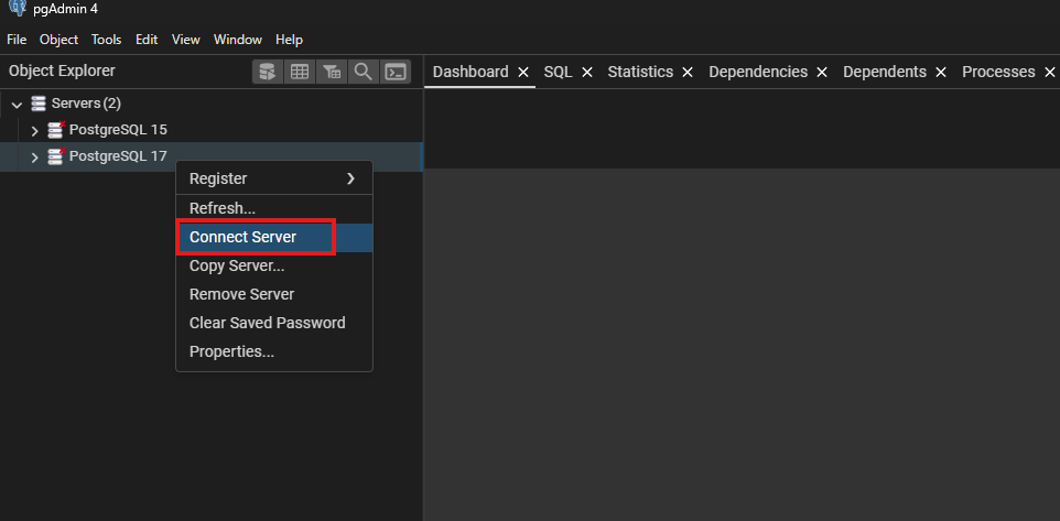
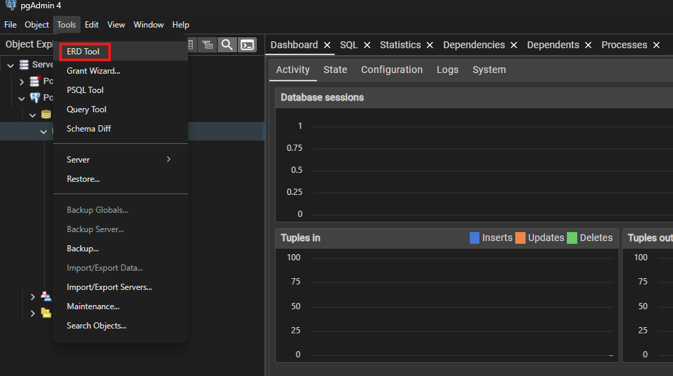
- Open ERD Tool:
- In the main pgAdmin window, from the menu bar select Tools > ERD Tool.
- An empty canvas will open in a new tab where you can design your ER diagram.
Step 2: Create a New ERD Project and Add Your First Table
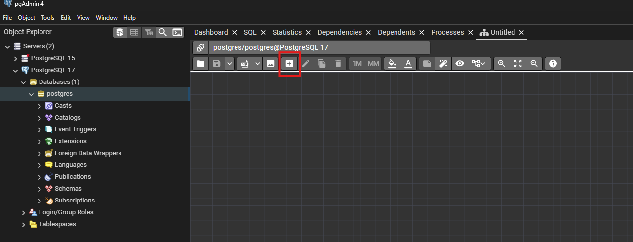
- Add a Table:
- Click the Add Table button (usually represented by a plus icon on the toolbar).
- A dialog window will appear asking for table details.
- Define Table Properties:
- Table Name: Enter a descriptive name (e.g.,
Employee).
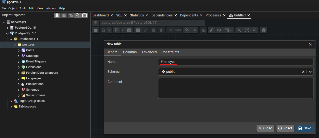
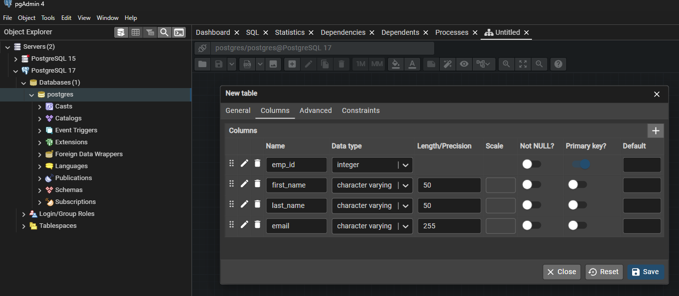
- Columns Tab: Switch to the Columns tab.
- Add columns one by one by clicking the “Add” (or plus) icon.
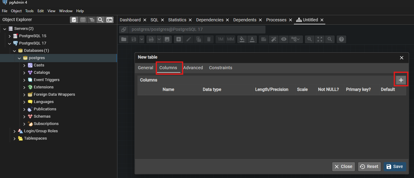
- For example, add:
emp_id (data type: integer, set as Primary Key),first_name (data type: character varying),last_name (data type: character varying),email (data type: character varying).
- Save the Table: Click Save to add the table to the canvas.
Step 3: Add a Second Table and Define Its Structure
- Repeat the Process:
- Click the Add Table button again.
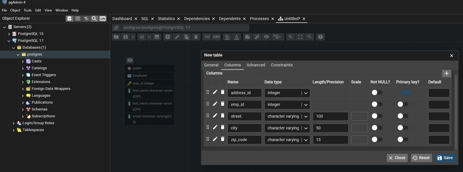
- Create a second table (e.g.,
Employee_Address) with columns such as:
address_id (data type: integer, set as Primary Key),emp_id (data type: integer, to link with the Employee table),street (data type: character varying),city (data type: character varying),zip_code (data type: character varying).
- Save the Second Table:
Click Save. The new table will appear on the ERD canvas.
- If tables overlap, use drag-and-drop to reposition them.
Step 4: Establish Relationships Between Tables
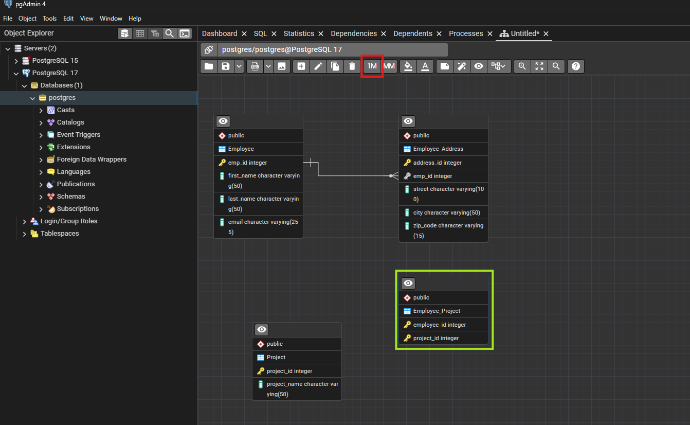
- Define a Foreign Key Relationship:
- Select the Table: Click on the
Employee_Address table node.
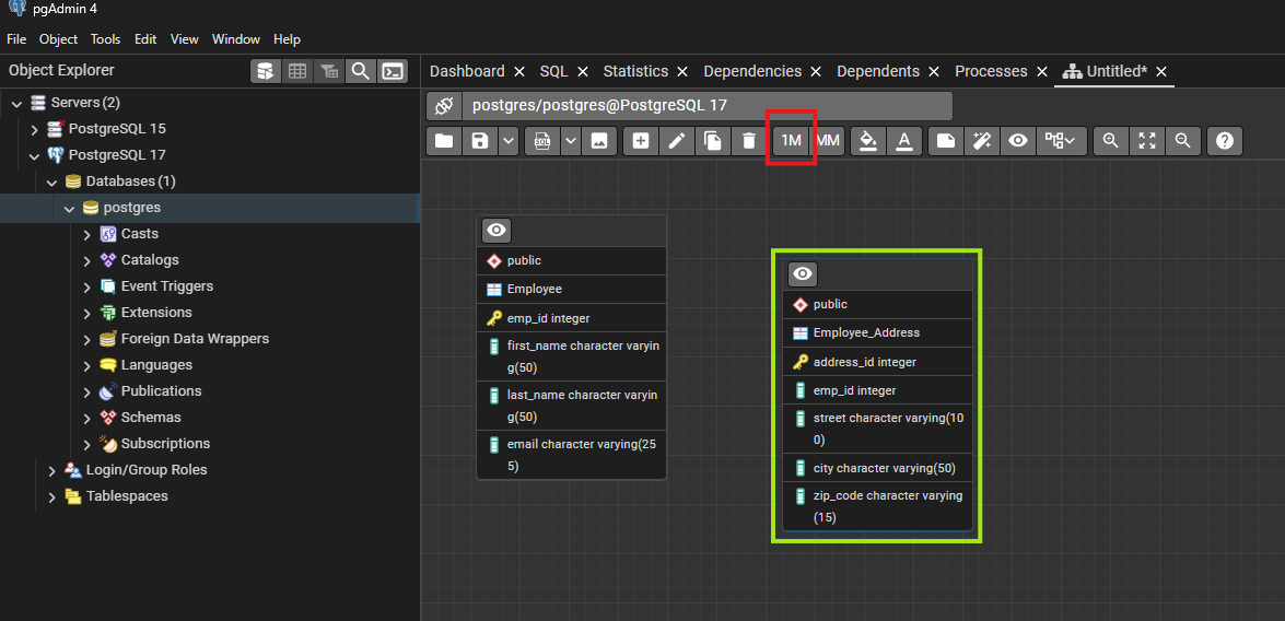
- Initiate Relationship Creation:
- Click on the 1M (one-to-many) button on the toolbar. This signifies that one record in the
Employee table can link to multiple addresses.
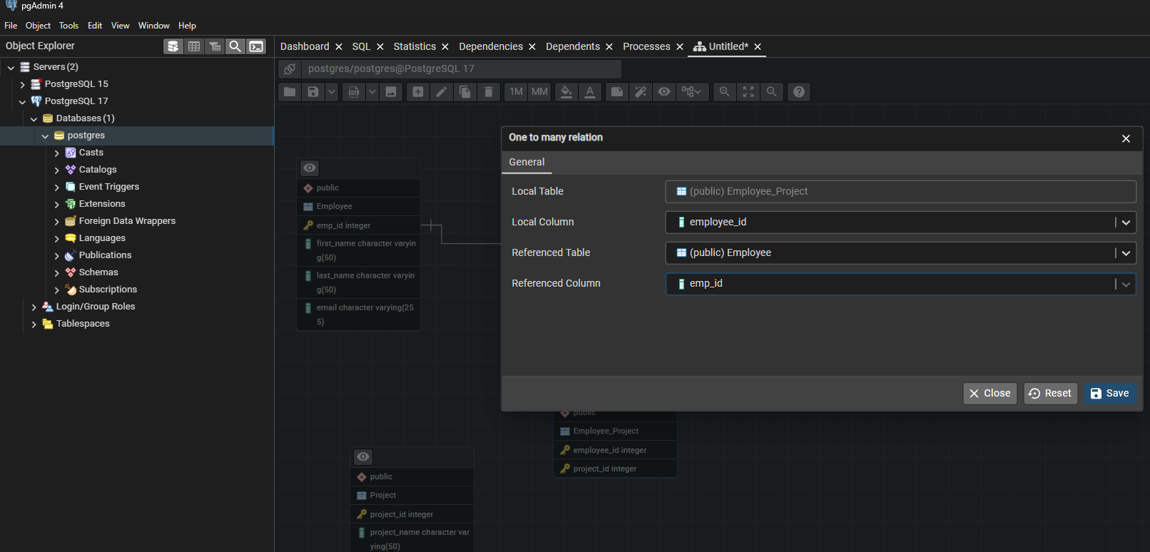
- Fill in the Relationship Dialog:
- Local Table:
Employee_Address
- Local Column: Select
emp_id (the column that will store the reference).
- Referenced Table:
Employee
- Referenced Column: Select
emp_id (the primary key in the Employee table).
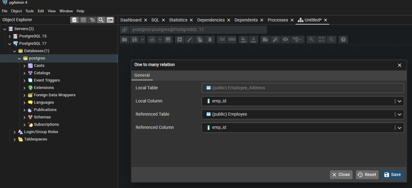
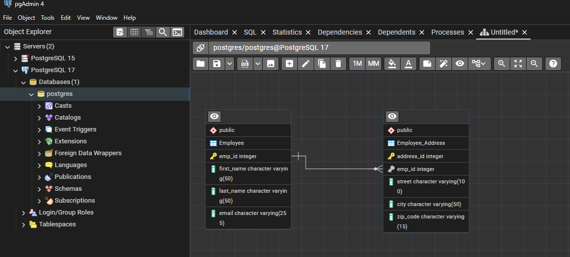
- Save the Relationship:
Once confirmed, a connecting line appears between the two tables, graphically representing the foreign key constraint.
Step 5: Create a Project Table
- Add a Table:
- Click the Add Table button.
- A dialog window will appear asking for table details.
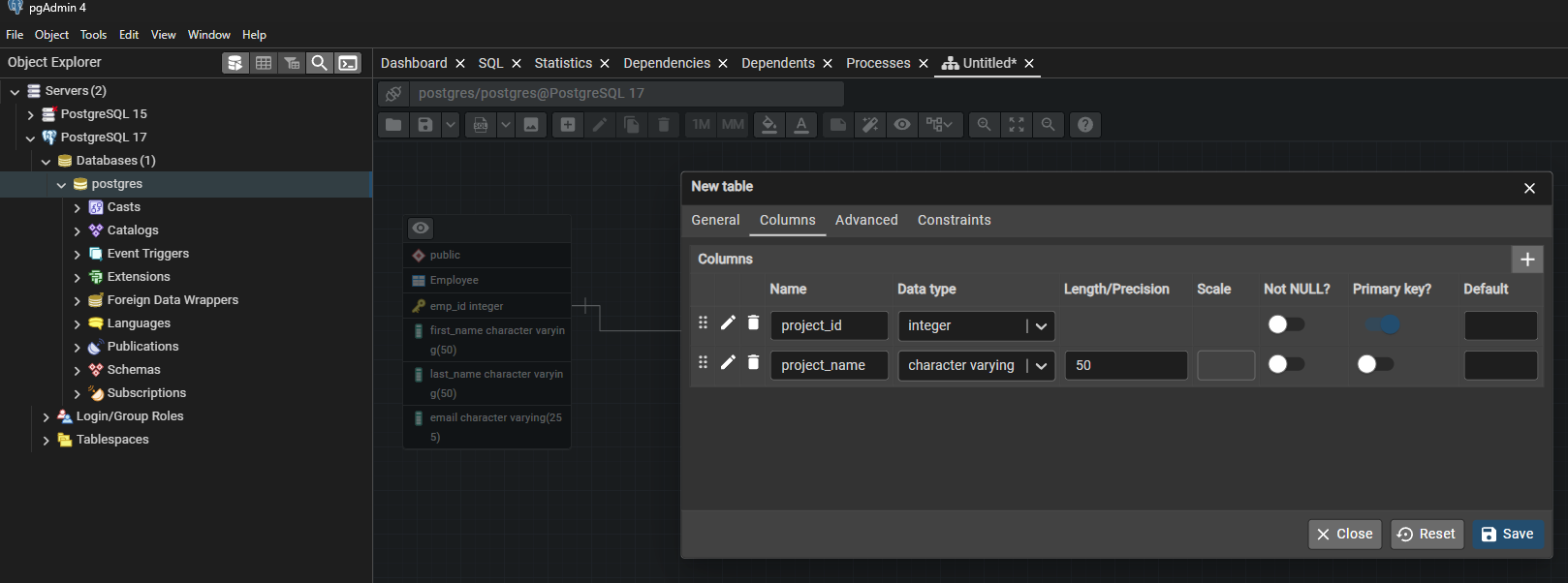
- Define Table Properties for the Project Table:
- Table Name: Enter
Project.
- Columns Tab: Add columns such as:
project_id (data type: integer, set as Primary Key),project_name (data type: character varying).
- Save the Project Table:
Click Save. The Project table will now appear on the ERD canvas.
Step 6: Creating a Many-to-Many Relationship
- Create an Intersection Table:
- Click the Add Table button.
- Name it
Employee_Project (this table will link employees to projects).
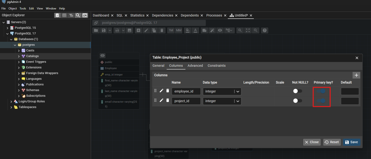
- Add columns:
employee_id (data type: integer, foreign key referencing Employee(emp_id)),project_id (data type: integer, foreign key referencing Project(project_id)).- Set both columns as a composite primary key by selecting them together.
- Define the Relationships:
- Link
Employee_Project.employee_id to Employee.emp_id (one-to-many relationship).
- Link
Employee_Project.project_id to Project.project_id (one-to-many relationship).
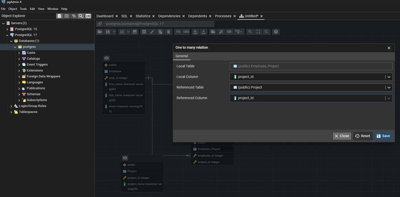
- This setup ensures that an employee can be assigned to multiple projects and a project can have multiple employees, forming a many-to-many relationship.
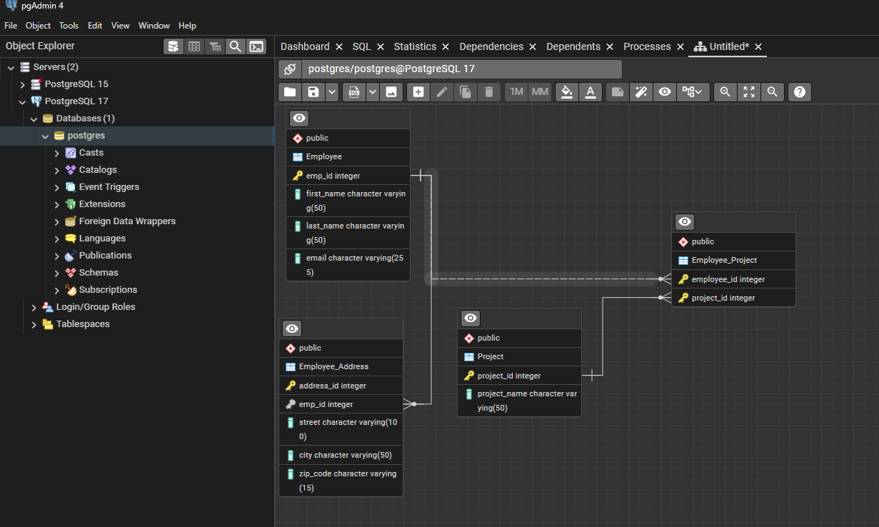
- Save and Review the Diagram:
- Ensure that the relationships are correctly represented with connecting lines.
Step 7: Enhance the ERD with Additional Features
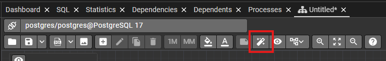
- Auto-Align Tables:
- Click the Auto Align icon on the toolbar to tidy up the layout. This rearranges the tables for clearer visualization.
- Add Notes & Color Coding:
- Use the Add/Edit Note button to attach annotations to tables.

- Change node colors with the Fill Color option to group related tables or highlight specific sections.

- Generate SQL DDL:
- Click the Generate SQL button (SQL icon).
- A query tool window opens with the SQL Data Definition Language (DDL) script generated from your diagram.
- This SQL can be used to recreate the database schema.

- Save Your ERD Project:
- Click the Save icon or use the shortcut (Ctrl + S).
- Provide a file name and choose a location to save your ERD diagram so that you can re-open and edit it later.